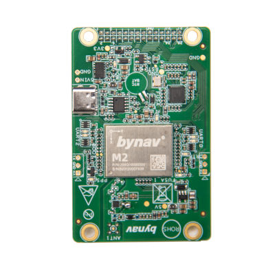
ByNav C2-M2X Evaluation Board / RTK USB GNSS Receiver (USB-C, M20 RTK GNSS Module included, Triple-band L1, L2 and L5, 1507 Channels, 1cm accuracy)
ByNav C2-M2X Evaluation Board / RTK USB GNSS Receiver (USB-C, M20 RTK GNSS Module included, Triple-band L1, L2 and L5, 1507 Channels, 1cm accuracy)
Country of Origin: China
Couldn't load pickup availability
Volume Discount Table
| Minimum Qty | Discount |
|---|---|
| 2 + | 5% off |
| 5 + | 6% off |
| 10 + | 7% off |
| 100 + | 9% off |
Bynav C2-M2X Evaluation Board / RTK USB GNSS Receiver, an all-in-one solution designed for efficient testing of the M20 (M2 series) modules. For details of the M20 modules, please refer to the M20 product page on our website.
This comprehensive kit, ideal for both professionals and enthusiasts, offers an easy setup and user-friendly experience. It includes all necessary tools and parts for effective testing and utilization of M20 modules, leveraging the robust M20 module for enhanced GNSS functionality. The kit comes with the "By_Connect" Windows software which provides real-time data visualization and configuration, ensuring a seamless experience when testing the M20 module.

(By_Connect Screenshot with C2-M2X EVB board connected.)
Contents of the Kit
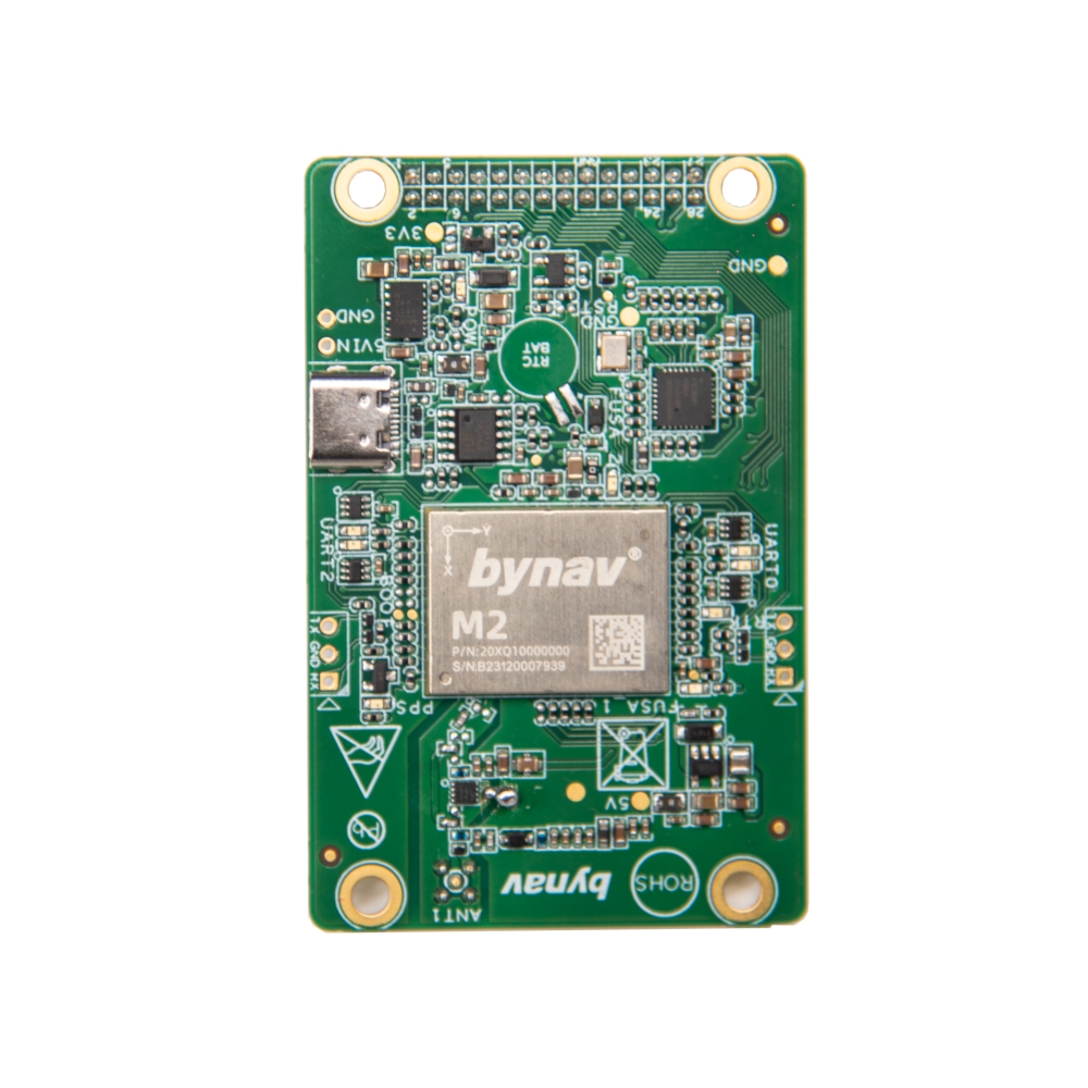
C2-M2X EVB Board with M20 Module:
The heart of the kit, the C2-M2X EVB Board, comes equipped with the M20 module. This integration provides a robust platform for testing various functions of the M20 module.
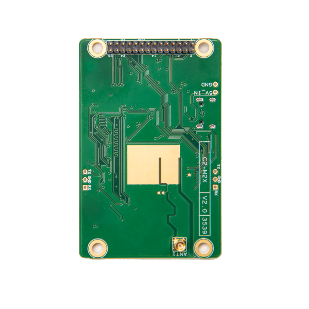
The board includes essential components like a 3.3V step-down circuit, a 5V boost circuit, RTC circuit, UTAR to USB circuit, RMII circuit, RF reception circuit, and a low-noise amplification circuit.
Various external interfaces are also part of the board, enhancing its versatility.
By_Connect Software:
This software communicates M20 to Computer through usb/ virtual serial ports, enabling real-time input correction data and output positioning data.
It graphically displays observable satellite sky maps and satellite signal-to-noise ratios.
The software facilitates the configuration of various receiver settings through console commands and save of the receiver's output data to a file.
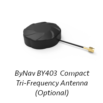
BY403 Compact Tri-Frequency Antenna for RTK Rover: (optional accessory)
The BY403, a compact, tri-frequency external antenna, is ideally suited for use as an RTK Rover antenna. For optimal performance, it should be placed in a stable, unobstructed location. When using indoors, ensure that the RF signal can penetrate effectively for reliable results.
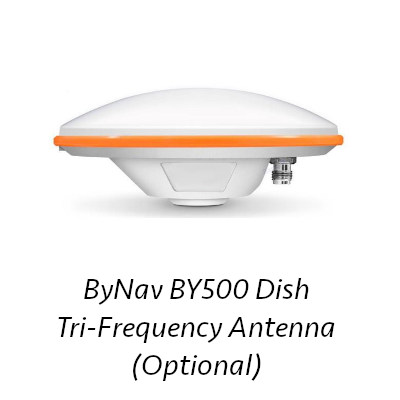
BY500 Dish shape Tri-Frequency Antenna for RTK Base: (optional accessory)
The BY500, with its dish-shaped design and tri-frequency capability, is an excellent choice for an RTK Base antenna. To achieve optimal performance, it should be positioned in a stable location free from obstructions.
 (Data file saved by By_Connect and dragged to RTKplot)
Connectivity and Power Supply
The C2-M2X EVB can be easily connected to a Windows computer through a Type-C USB connection, which serves both for power supply and data communication.
Before use, it is necessary to install the USB driver program CH340/341 (download link: CH340/341 Driver).
Post installation, two virtual COM ports will be recognized in the Device Manager for efficient communication and data transfer.
 Installation and Setup
Ensure the GNSS antenna is connected to the development board using the provided RF coaxial cable. Use a Type-C data cable to connect the C2-M2X to a Windows computer. The kit comes with necessary cables for a hassle-free setup.
Precautions for Using the C2-M2X EVB
The C2-M2X EVB is designed for use in laboratory or engineering development settings. To ensure safe and efficient operations, please adhere to the following precautions:
Avoid Hot-Plugging:
Do not perform hot-plugging on the development board's interfaces or on any carrier boards. Connecting or disconnecting components while the board is powered can cause damage.
Electrostatic Discharge (ESD) Protection:
Electrostatic discharge can harm the development board's hardware. Employ necessary anti-static measures, such as using an ESD wrist strap, before unpacking and handling the board.
Safe Handling of the Board:
When handling the development board, grasp it by the edges to minimize the risk of ESD damage. Avoid direct contact with any exposed metal parts on the board.
Optimal Placement:
Place the C2-M2X development board on a stable, dry, and flat surface. Ensure it is positioned away from heat sources, sources of electromagnetic interference, radiation sources, and equipment sensitive to electromagnetic radiation, such as medical devices.
By following these precautions, you can help ensure the longevity and proper functioning of your C2-M2X EVB.
Product Resources
Official Documents:
YouTube Videos:
How to Articles and Blogs:
Tech Support Topics and Forums:
