GeoAstra ANT506 high-precision built-in GNSS antenna (L1 L2 multi-frequency, multi-feed point
GeoAstra ANT506 high-precision built-in GNSS antenna (L1 L2 multi-frequency, multi-feed point
Country of Origin: China
Couldn't load pickup availability
Volume Discount Table
| Minimum Qty | Discount |
|---|---|
| 2 + | 5% off |
| 5 + | 6% off |
| 10 + | 7% off |
| 100 + | 9% off |
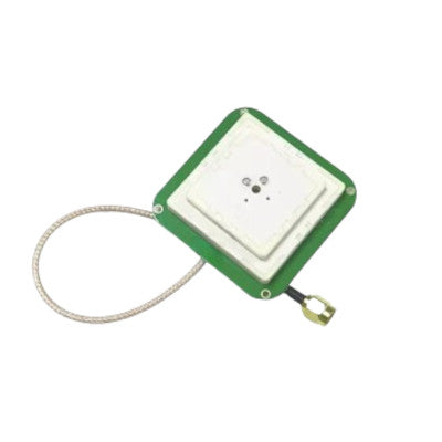
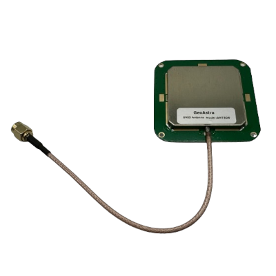
The GeoAstra ANT506 is a built-in GNSS antenna designed for the L1, L2 dual band RTK GNSS modules (such as ZED-F9P), offering high-precision GNSS reception with L1 and L2 dual dielectric ceramic antennas. Compact at 55x55x15mm, it integrates easily with other GNSS modules, maintaining excellent GNSS performance. This industrial-grade antenna is compatible with various satellite navigation receivers and is widely used in geodetic surveying, waterway mapping, precision agriculture, and maritime measurement. Featuring multi-feed point design, high gain, wide beam width, and resistance to multipath effects, the ANT506 ensures accurate and reliable GNSS data, even in challenging environments.
Key Features:
Using Multi Feed Point Design
• Multi Feed Point Design: This technology involves placing multiple feed points in the antenna structure. Each feed point is a location where the signal enters or exits the antenna.
• Superposition of Phase Center and Geometrical Center: The phase center is the point where the signals seem to originate, and the geometrical center is the physical center of the antenna. Ensuring these two points coincide (superpose) is crucial for accurate signal reception.
• Minimizing Measurement Error: When the phase center and geometrical center are aligned, it reduces variations in the received signal, thus minimizing measurement errors. This alignment ensures that the antenna receives signals more uniformly, enhancing overall positioning accuracy.
High Gain and Direction Map Beam Width
• High Gain of the Antenna Element: Gain refers to the ability of the antenna to focus signal reception in a particular direction. High gain means the antenna can effectively receive weak signals from satellites, enhancing sensitivity and performance.
• Direction Map Beam Width: This refers to the range of angles over which the antenna can effectively receive signals. A wider beam width means the antenna can capture signals from a broader range of angles.
• Receiving Satellites Performance of Low Elevation Mask: Low elevation satellites are those near the horizon. High gain and wide beam width ensure that the antenna can effectively receive signals from these low elevation satellites, which are often more challenging to capture. This improves the number of satellites the antenna can use, enhancing positioning accuracy and reliability.
Resistance to Multipath Effects
• Multipath Effects: Multipath occurs when signals reflect off surfaces (such as buildings or the ground) before
Technical Specifications:
GPS
• L1/L2
GLONASS
• L1/L2
BEIDOU
• B1/B2
GALILEO
• E1/E5b
QZSS
• L1
SBAS
• L1
Polarization
• RHCP (Right-Hand Circular Polarization)
Antenna Axial Ratio (dB)
• ≤ 1.5 dB
Impedance
• 50 ohm
Frequency Range
• 1197 MHz ~ 1278 MHz
• 1559 MHz ~ 1606 MHz
LNA Gain
• 35 ± 3.0 dB (Typ. @ 25°C)
Noise Figure (dB)
• ≤ 1.5 dB @ 25°C
Output VSWR
• 1.8:1 typ. 2.0:1 max
Operation Voltage
• 3.0 ~ 12V DC
Operation Current
• < 45 mA
Product Size
• 55 mm * 55 mm * 15 mm
Connector
• SMA-J
Weight
• < 78 g
Cable Length
• 15 cm (customizable)
Operating Temperature
• -40°C ~ +70°C
Storage Temperature
• -55°C ~ +85°C
Dimensions (mm):


